When owners of the Wanhao Duplicator i3 (or its relatives, like my Monoprice Maker Select) want to build a DIY enclosure, a popular method is to start with an IKEA Lack end table. Add a base, some combination of sidewalls/doors, and a bit of optional PTFE tubing to guide your filament inside, and you have a decent enclosure.
This is a fairly inexpensive method so long as you have an IKEA nearby. The Lack is super cheap (<$10), primarily because it isn’t made from solid wood, but rather a thin veneer around a hollow particleboard shell, filled with a cardboard honeycomb. Th enearest IKEA is over an hour away, but my friends were going to browse furniture, so I asked them to grab me two Lacks.
Each table is 21.625 inches on a side and is 17.75 inches tall. Since the top is 2 inches thick, the legs come in at 15.75 inches long. At 15.375 inches, the gantry of a stock Wanhao type printer just barely fits within this space. It’s even closer if you’ve performed AzzA’s Z brace mod (due to the printer being raised about a quarter inch by the feet on the Y axis assembly).
One quirk of these printers is that the print head has issues near the top bar, making nearly 40 mm of the rated 180 mm height dodgy at best, and potentially a fire hazard (due to wires getting severed and shorting out) at worst. I wanted to add AzzA’s Z extensions to recover this height, but that would definitely make the printer too tall for the Lack. I needed longer legs for the table, or failing that, extensions.
I obtained the second Lack with the idea of using part of its legs as extensions, and its top as the base of the enclosure. It turns out that you can’t just saw off a short section of one set of legs and glue that to the other set. Similar to the table itself, each leg is composed of a 3 mm shell of wood along its length, with a roughly half-inch tall block of particleboard capping either end. (I tapped on the leg to determine where the sound changed as the caps ended). There is a hole at one end for the double-ended screw that attaches it to the underside of the table.
But the legs are 2 inches wide, so surely all we need is a 2 x 2 inch block of wood under each leg, right?
Unfortunately, that’s easier said than done. Lumber from home improvement stores is not dimensionally accurate, meaning that a nominally 2 x 2 inch width is actually more like 1.5 x 1.5 inches. That won’t work for extensions unless you can find a (larger) nominal size in stock that measures exactly 2 x 2 (a chart I saw suggests nominal 2.5 x 2.5 inch lumber would work, but that wasn’t carried at the store).
You could rip down a larger piece of wood, like a 4 x 4 or whatever, but I don’t have the equipment or space for that, and it’d probably take a fair bit of finishing. Non-dimensionally accurate lumber would also be perfectly acceptable if you didn’t mind entirely replacing the Lack legs, but you’d probably need to plane the faces if aesthetics were a concern or the wood is bowed.
You’d also need to decide whether to fit smaller legs flush with the edge of the table like the originals (in which case you’ll need an alternate method of attaching them), or inset (in which case the side walls and door are a little more complex). If you were going to go to all the effort of these solutions, you might as well just build the entire enclosure from scratch.
Legging It
The solution to this conundrum seems obvious: Design and print extensions for the legs, like little stilts. So I’ve set out to do just that.
Note: the following info is for historical interest. Right after I got my the first extension printed, I found this design, which I liked better than my own because it allowed for the top of the enclosure to be removed without undoing screws or sacrificing stability.
I am designing this part to add 2 inches of height to the Lack legs. That’s more than I need for the Z extension mod (which adds 37 mm, about 1.5 inches). As the point of an enclosure is primarily to retain heat, this will probably be best printed in a high temperature material. I’m testing with PETG.
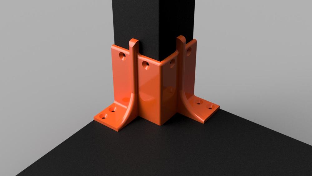
The part attaches to the leg by screwing into the bottom particleboard cap, using inch long #8 flathead wood screws. Only three screws are needed at the top — one in each of the outer holes, and one in either of the holes near the middle of the image. There are four holes mainly to avoid the need to print mirrored parts. You could add a shorter fourth screw to the last middle hole if desired, but inch-long screws won’t fit in both of them, as they’d hit each other inside the leg.
Vertically, the part screws down into the base of the enclosure with 4 more screws. If you use a second Lack as the base, these holes should match up with the table’s internal particleboard frame.
Because these screw into particle board, I can’t recommend treating the enclosure as capable of holding the weight of the printer (in other words, take the machine out before lifting on any part of the enclosure other than the base). The extensions mostly just need to bear the weight of the Lack table, or possibly to keep it from blowing away in a stiff wind. They also keep it aligned to the base of the enclosure.
Here is the render of the enclosure, sans mounting hardware like screws and hinges for the door.
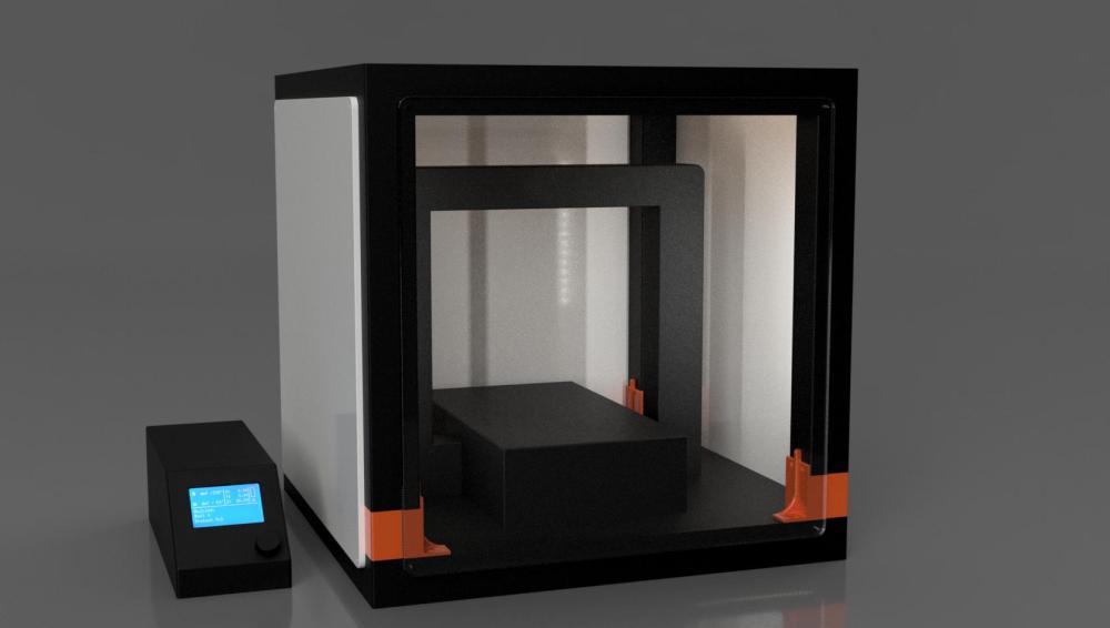
Forgive the crudity of the printer model; I didn’t feel like reproducing the entire thing in CAD. The printer shown is the stock height, and doesn’t include the extra height I’ll have from the Z extensions.
The orange color of the extension parts is mostly just to distinguish them from the table. My extensions will be printed in black. I’ll be posting the STL to the usual sites once I have the design nailed down and tested.
